
How to Test a Relay with a Multimeter: A Practical Step-by-Step Guide
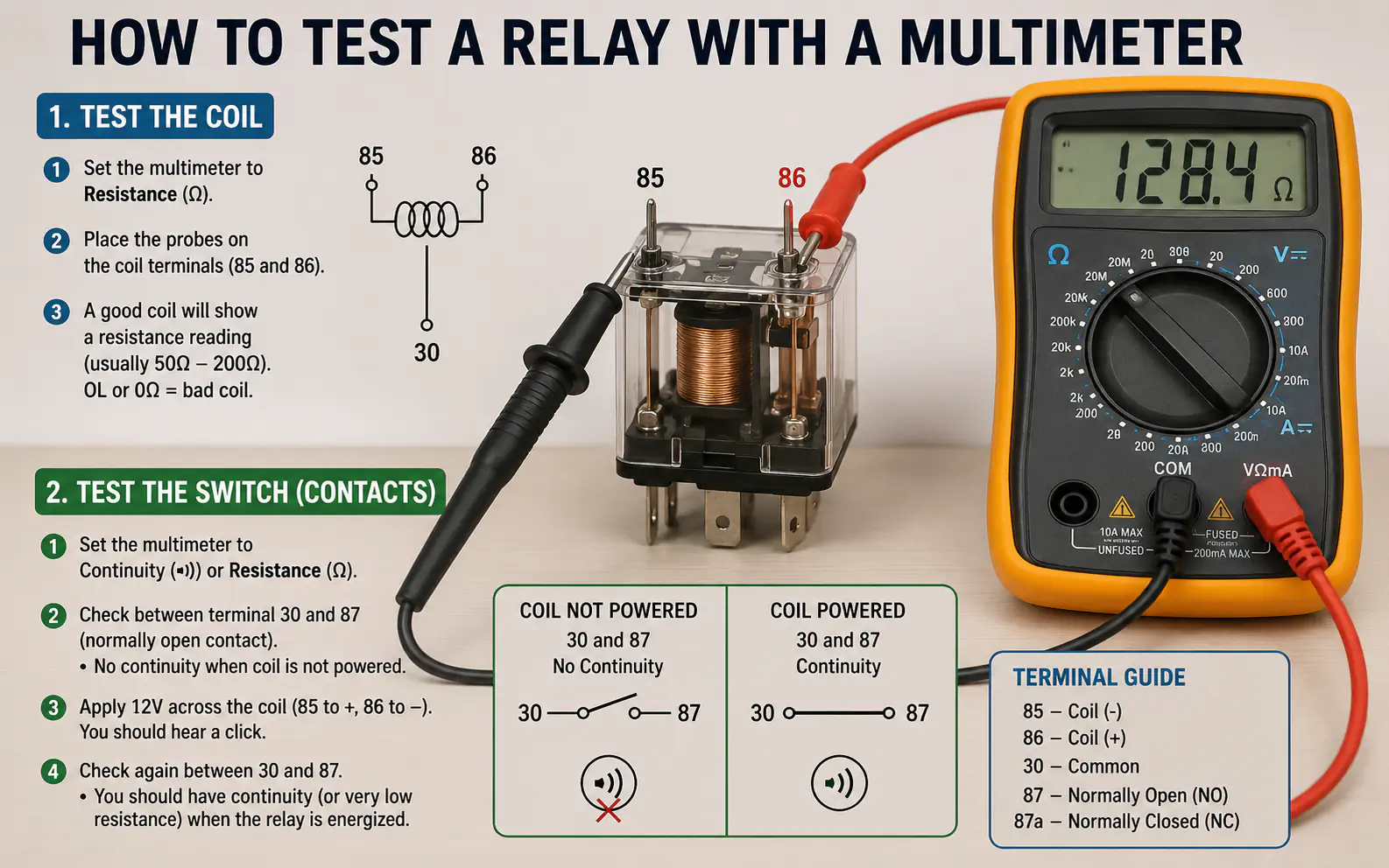
Testing a relay with a multimeter involves checking two distinct parts: the internal coil and the switch contacts. If the coil is burned out or the contacts are stuck, the relay will fail to operate, often causing the connected device to stop working entirely.
To perform this test, you will need a digital multimeter set to the resistance (Ohms) setting. By measuring the resistance across the coil pins and checking for continuity across the switch pins, you can quickly determine if the relay is the source of your electrical problem.
Setting the multimeter to resistance
- Always disconnect power before testing.
- The coil should show specific resistance, not zero or infinity.
- The switch side should show continuity only when the relay is activated (or normally closed).
- A relay that clicks isn’t always a good relay.
| Topic | When it helps | What to keep in mind |
|---|---|---|
| Step 1 | All relay testing scenarios. | Never test a relay while it is still connected to a live power source. |
| Step 2 | Verifying the electromagnetic trigger. | A reading of ‘OL’ or ‘1’ indicates an open circuit (broken coil). |
| Step 3 | Checking if the switch is stuck. | If it beeps without power, the contacts are fused shut. |
| Step 4 | Final diagnosis. | Don’t assume a clicking sound means the relay is good; the contacts inside might still be burnt. |
Focus strictly on the multimeter
Step 1. Safety and Preparation
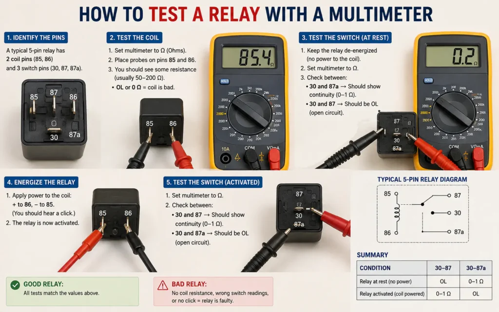
Ensure the relay is removed from the circuit and the power source is disconnected. Locate the pin diagram printed on the side of the relay to identify which pins are for the coil and which are for the switch.
- All relay testing scenarios.
- Never test a relay while it is still connected to a live power source.
- If the relay has no diagram, look for the manufacturer part number online to find the pinout.
- Tool – Multimeter
- Setting – Resistance (Ω)
Step 2. Testing the Coil Resistance
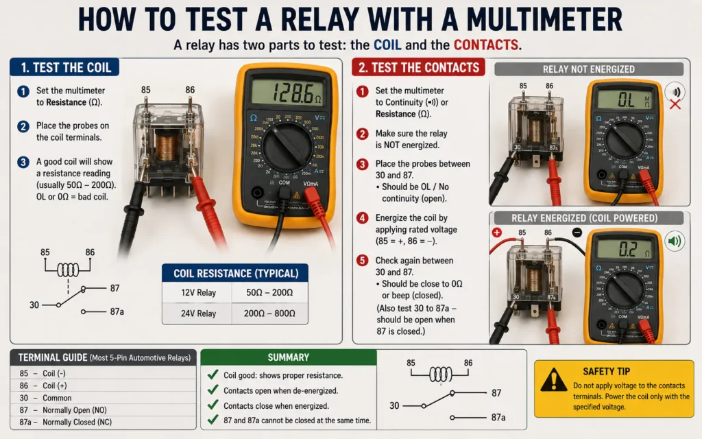
Set your multimeter to the 200 or 2k Ohm range. Place one probe on each of the coil pins (typically labeled 85 and 86). A healthy relay usually shows a resistance between 50 and 120 Ohms.
- Verifying the electromagnetic trigger.
- A reading of ‘OL’ or ‘1’ indicates an open circuit (broken coil).
- If you see 0 Ohms, the coil is shorted internally.
- Expected – 50-120 Ohms
- Failure – OL or 0
Step 3. Testing the Switch Contacts
Switch your multimeter to the continuity (beep) mode. Test the switch pins (typically 30 and 87). In a standard ‘normally open’ relay, you should hear no beep until the relay is energized.
- Checking if the switch is stuck.
- If it beeps without power, the contacts are fused shut.
- If you have a 12V power source, you can apply it to the coil pins to hear the ‘click’ and then test for continuity.
- Mode – Continuity/Beep
- State – Normally Open
Step 4. Interpreting Results
Compare your findings against the expected values. If the coil resistance is out of range or the switch contacts fail to close when energized, the relay is faulty and should be replaced.
- Final diagnosis.
- Don’t assume a clicking sound means the relay is good; the contacts inside might still be burnt.
- When in doubt, compare the reading to a known good relay of the same part number.
- Action – Replace if failed
- Confidence – High
Understanding Relay Pinouts
Before you touch your probes to the pins, you must identify their purpose. Most relays have a small schematic printed on the side. This diagram shows you exactly which pins connect to the internal coil and which connect to the switch contacts.
If the relay is old or the print has worn off, search for the part number online. Using the wrong pins will result in inaccurate readings and could potentially damage your multimeter if you accidentally test a live circuit.
Most automotive relays use standard numbering: 85 and 86 for the coil, 30 for common power, and 87 for the output.
Do not guess the pin functions based on position alone; always verify the diagram on the relay casing.
- 85 & 86: Coil terminals (the trigger).
- 30: Common power input.
- 87: Normally open output.
- 87a: Normally closed output (if present).
| Test Type | Multimeter Setting | What to Look For |
|---|---|---|
| Coil Test | Ohms (Resistance) | Stable reading (50-120Ω) |
| Switch Test | Continuity (Beep) | No beep (unless energized) |
Troubleshooting Common Relay Failures
A relay can fail in two main ways: the coil can burn out, or the switch contacts can weld together or become pitted. The coil test tells you if the electromagnet is still capable of pulling the switch closed.
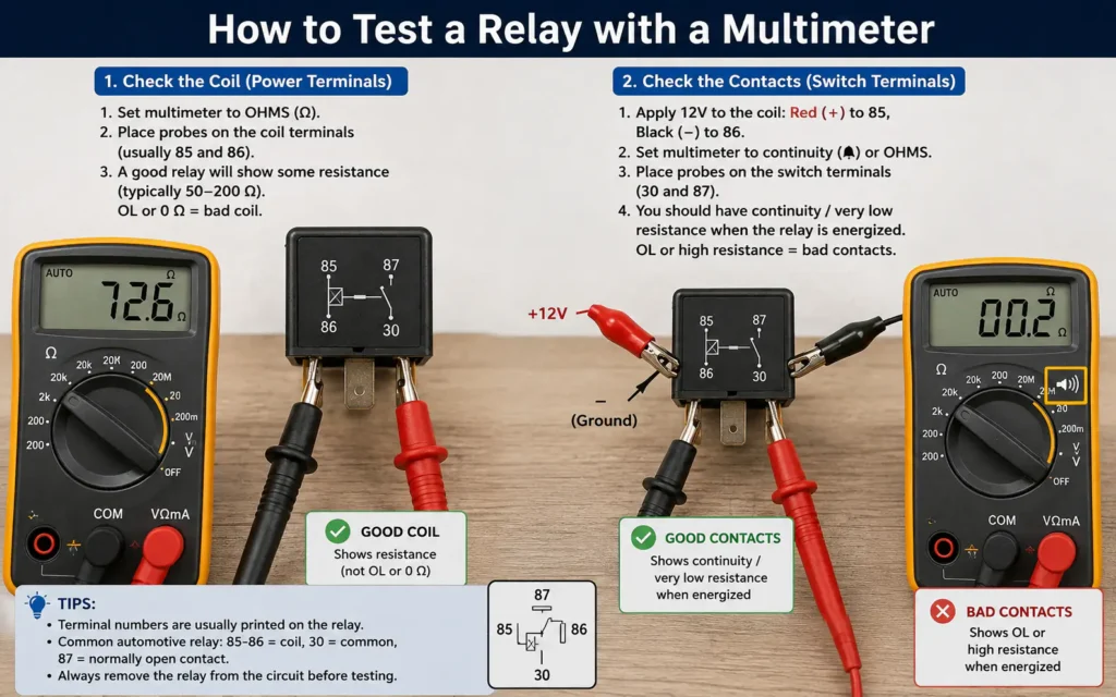
The switch test is equally important. Even if the coil works, the metal contacts inside the relay can become carbonized or pitted over time. This prevents electricity from flowing through the switch, even when the relay is ‘on’. If you hear a click but the device doesn’t turn on, the contacts are likely the culprit.
If your headlights flicker, the relay contacts might be pitted, causing intermittent continuity even if the coil tests fine.
Assuming a relay is good just because it clicks; the internal contacts can be burnt even if the coil works.
- Coil failure: Often caused by heat or age.
- Contact failure: Often caused by high current arcing.
- Intermittent operation: Usually a sign of pitted contacts.
FAQs
How do I know if my relay is bad with a multimeter?
If the coil shows ‘OL’ (infinite resistance) or 0 Ohms, it is bad. If the switch contacts do not show continuity when the relay is energized, the relay is also faulty.
How to test a 4 pin relay with a multimeter?
A 4-pin relay is tested the same way as a 5-pin, just without the 87a pin. Test the two coil pins for resistance and the two switch pins for continuity.
How many ohms should a relay test?
Most standard 12V automotive relays test between 50 and 120 Ohms across the coil pins. Always check the manufacturer’s specs if available.
What does ‘OL’ mean on my multimeter?
OL stands for ‘Open Loop’ or ‘Out of Limits.’ In a resistance test, it means there is no electrical path, indicating a broken wire or burnt-out coil.
Conclusion
Testing a relay is a straightforward process that can save you from replacing expensive components unnecessarily. By isolating the coil and switch circuits, you can quickly verify if the relay is the true source of your electrical issue.
Always remember to verify your pinout diagram before testing. If your readings fall outside the expected ranges or show signs of an open circuit, it is time to replace the relay with a new one of the same specifications.
Related posts
 How to Strengthen Weak Nails: A Practical Guide to Daily Care
Learn how to strengthen weak nails with simple daily habits, protective care, and targeted hydration. Restore your natural nail strength today. Weak, peeling, or brittle nails…
 What Sounds Do Cats Dislike? 7 Noises That Stress Your Pet
Discover what sounds do cats dislike and why. Learn how to protect your cat’s sensitive hearing from stressful household noises and high-frequency hums. Cats dislike sounds…
 Restoring Faded Black Clothing: Practical Methods and Reality Checks
Can you restore faded black clothing? Learn the difference between temporary color revival and permanent redyeing, plus how to prevent future fading. You can restore the…