
How to Check Voltage Drop in Automotive Wiring: A Practical Guide
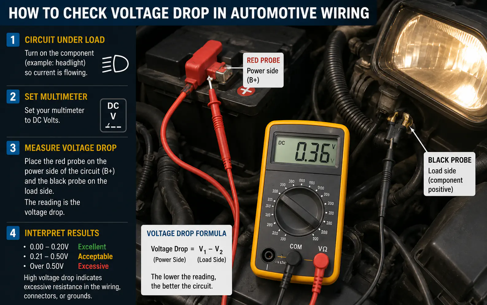
Checking for voltage drop is the most reliable way to find hidden electrical resistance in your car’s wiring. Unlike a simple continuity test, a voltage drop test measures how much energy is lost as electricity travels through a wire or connection, helping you pinpoint exactly where corrosion or damage is restricting power.
To perform this test, you will need a digital multimeter set to DC voltage. You must test the circuit while it is turned on and under load, such as when the headlights are shining or the fuel pump is running. If you measure a significant difference in voltage between two points on the same wire, you have found your point of failure.
Safety checks
- Always perform the test while the circuit is active (under load).
- A voltage drop of 0.1V to 0.3V is generally acceptable for most connections.
- Testing the ground side is just as important as testing the power side.
- Never rely on resistance (Ohms) testing for high-current circuits.
| Topic | When it helps | What to keep in mind |
|---|---|---|
| Step 1 | All standard 12V automotive systems. | Do not set the meter to Ohms (Ω) or Amps (A) for this test. |
| Step 2 | Finding resistance that only appears when current is flowing. | Testing a dead circuit will not show a voltage drop. |
| Step 3 | Identifying issues in the power feed wiring. | Ensure good contact; use piercing probes if necessary. |
| Step 4 | Finding poor chassis grounds or corroded ground straps. | Do not touch the leads together while testing. |
Focus strictly on the voltage
Step 1. Prepare the Multimeter
Set your multimeter to the DC Voltage (V) setting. Choose a range that can read at least 20V, or use the auto-ranging feature.
- All standard 12V automotive systems.
- Do not set the meter to Ohms (Ω) or Amps (A) for this test.
- Ensure your test leads are securely connected to the meter ports.
Step 2. Activate the Circuit
Turn on the component you are testing. If you are testing headlights, turn them on. If testing a fuel pump, ensure the ignition is in the ‘run’ position.
- Finding resistance that only appears when current is flowing.
- Testing a dead circuit will not show a voltage drop.
- If the component won’t turn on, use a jumper wire or bypass to simulate the load.
Step 3. Measure the Positive Side
Place the red lead on the battery positive terminal and the black lead on the power input side of the component.
- Identifying issues in the power feed wiring.
- Ensure good contact; use piercing probes if necessary.
- A reading higher than 0.5V indicates excessive resistance.
Step 4. Measure the Ground Side
Place the red lead on the component’s ground connection and the black lead on the negative battery terminal.

ul>
Interpreting Your Voltage Drop Readings
Voltage drop is essentially the ‘tax’ paid by electricity to travel through a wire. In a perfect world, a wire would have zero resistance, but in reality, every connection and length of wire adds a tiny amount of resistance.
When you see a high number on your meter, it means the wire is struggling to push the current through. This energy is converted into heat rather than powering your component.
If you measure 2.0V across a headlight wire, that is a clear failure; the light will be dim because the wire is ‘stealing’ the voltage.
Assuming 0V is the only ‘good’ reading; some minor drop is normal due to wire length.

| Voltage Drop Reading | Status |
|---|---|
| 0.0V – 0.1V | Excellent (Like new) |
| 0.1V – 0.3V | Acceptable (Minor wear) |
| 0.3V – 0.5V | Marginal (Needs inspection) |
| Above 0.5V | Failed (Repair required) |
Common Mistakes to Avoid
Many beginners make the mistake of testing a circuit while it is disconnected. This is called an ‘open circuit’ test. While it tells you if you have power, it does not tell you if the wire is capable of handling the current required by the component.
Always ensure the circuit is closed and the component is drawing power. If the component is completely dead, you may need to use a test light or a known-good component to create the necessary load.
Testing a wire with the component unplugged will show 12V, but it won’t reveal if the wire can actually carry the load.
Testing without a load is the most common error in automotive diagnostics.
- Testing with the circuit turned off.
- Using the wrong multimeter setting (Ohms instead of Volts).
- Testing only the power side and ignoring the ground.
- Using poor contact points (like painted surfaces) for the probes.
FAQs
Why can’t I just use the Ohms setting on my multimeter?
The Ohms setting uses a tiny amount of current from the meter’s battery. It cannot detect resistance in a high-current circuit, which is where most automotive failures occur.
What if my multimeter reading is negative?
A negative reading simply means your leads are reversed. Swap the red and black leads, and the number will become positive.
Is it normal to have some voltage drop?
Yes. Every wire and connector has some inherent resistance. As long as the drop is below 0.3V, it is usually considered healthy for most automotive circuits.
Can I test voltage drop on a sensor circuit?
Yes, but be careful. Sensor circuits carry very low current. A voltage drop test is still valid, but ensure your meter has high input impedance to avoid affecting the sensor’s signal.
Conclusion
Mastering the voltage drop test is a fundamental skill that separates guesswork from accurate diagnostics. By focusing on how the circuit performs under load, you can quickly identify whether a component is truly faulty or if the wiring is simply failing to deliver the necessary power.
If you find a high voltage drop, inspect the connectors for corrosion, loose pins, or frayed insulation. Often, a simple cleaning or a new terminal is all it takes to restore full performance to your vehicle’s electrical system.
Related posts
 How to Strengthen Weak Nails: A Practical Guide to Daily Care
Learn how to strengthen weak nails with simple daily habits, protective care, and targeted hydration. Restore your natural nail strength today. Weak, peeling, or brittle nails…
 What Sounds Do Cats Dislike? 7 Noises That Stress Your Pet
Discover what sounds do cats dislike and why. Learn how to protect your cat’s sensitive hearing from stressful household noises and high-frequency hums. Cats dislike sounds…
 Restoring Faded Black Clothing: Practical Methods and Reality Checks
Can you restore faded black clothing? Learn the difference between temporary color revival and permanent redyeing, plus how to prevent future fading. You can restore the…